Solution 405 Click here to show or hide the solution Tags: moment diagram shear diagram shear and moment diagrams simple beam concentrated load Uniformly Distributed Load ‹ Solution to Problem 404 | Shear and Moment Diagrams up Solution to Problem 406 | Shear and Moment Diagrams › Add new comment 288322 reads More Reviewers
A Simply Supported Beam Loaded with more than Two Point Loads, the 2 nd… | Download Scientific Diagram
Step by step Solved in 2 steps with 1 images SEE SOLUTION Check out a sample Q&A here Knowledge Booster Learn more about Axial Load Need a deep-dive on the concept behind this application? Look no further. Learn more about this topic, mechanical-engineering and related others by exploring similar questions and additional content below.

Source Image: mathalino.com
Download Image
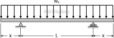
Beam Supported at Both Ends – Uniform Continuous Distributed Load. The moment in a beam with uniform load supported at both ends in position x can be expressed as. M x = q x (L – x) / 2 (2) where. M = moment in position x (Nm, lb in) x = distance from end (m, mm, in) The maximum moment is at the center of the beam at distance L/2 and can be

Source Image: chegg.com
Download Image
Find the support reactions of the beam loaded as shown in the figure. #mechanical #engineering – YouTube The simply supported beam is one of the most simple structures. It features only two supports, one at each end. One is a pinned support and the other is a roller support. With this configuration, the beam is inhibited from any vertical movement at both ends whereas it is allowed to rotate freely. Due to the roller support it is also allowed to

Source Image: dlubal.com
Download Image
A Beam Is Loaded And Supported As Shown
The simply supported beam is one of the most simple structures. It features only two supports, one at each end. One is a pinned support and the other is a roller support. With this configuration, the beam is inhibited from any vertical movement at both ends whereas it is allowed to rotate freely. Due to the roller support it is also allowed to Engineering Mechanical Engineering Mechanical Engineering questions and answers P11.3 A beam is loaded and supported as shown in Figure P11.3. (a) Use the double-integration method to determine the reactions at supports A and B. (b) Draw the shear-force and bending- moment diagrams for the beam. FIGURE P11.3 This problem has been solved!
Moment Interaction Diagrams in RFEM 6 | Dlubal Software
5 days agoA beam is loaded and supported as shown, with M = 3 0 0 0 ft * lb, w 1. = 1 9 0 lb / ft and w 2. = 4 5 0 lb / ft. The dimensions on the figure are a = 5. 4 ft and b = 4. 3 ft. Draw and label shear and bending moment diagrams for this beam. From your diagrams, enter the following information. 5.68 Analysis & Design of Beam | Mechanics of Materials – YouTube

Source Image: youtube.com
Download Image
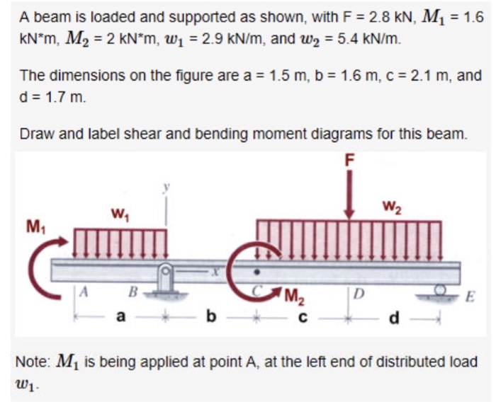
Solved A beam is loaded and supported as shown, with F = 2.8 | Chegg.com 5 days agoA beam is loaded and supported as shown, with M = 3 0 0 0 ft * lb, w 1. = 1 9 0 lb / ft and w 2. = 4 5 0 lb / ft. The dimensions on the figure are a = 5. 4 ft and b = 4. 3 ft. Draw and label shear and bending moment diagrams for this beam. From your diagrams, enter the following information.

Source Image: chegg.com
Download Image
A Simply Supported Beam Loaded with more than Two Point Loads, the 2 nd… | Download Scientific Diagram Solution 405 Click here to show or hide the solution Tags: moment diagram shear diagram shear and moment diagrams simple beam concentrated load Uniformly Distributed Load ‹ Solution to Problem 404 | Shear and Moment Diagrams up Solution to Problem 406 | Shear and Moment Diagrams › Add new comment 288322 reads More Reviewers

Source Image: researchgate.net
Download Image
Find the support reactions of the beam loaded as shown in the figure. #mechanical #engineering – YouTube Beam Supported at Both Ends – Uniform Continuous Distributed Load. The moment in a beam with uniform load supported at both ends in position x can be expressed as. M x = q x (L – x) / 2 (2) where. M = moment in position x (Nm, lb in) x = distance from end (m, mm, in) The maximum moment is at the center of the beam at distance L/2 and can be

Source Image: youtube.com
Download Image
A Simply Supported Beam Loaded with more than Two Point Loads the 1 st… | Download Scientific Diagram 3,508 solutions Advanced Engineering Mathematics 10th Edition • ISBN: 9780470458365 (1 more) Erwin Kreyszig 4,134 solutions Statics and Mechanics of Materials: An Integrated Approach 2nd Edition • ISBN: 9780471434467 Don H Morris, Leroy D Sturges, William F Riley 612 solutions More related questions engineering

Source Image: researchgate.net
Download Image
The beam supports the triangular distributed load shown below with wmax=500 lb/ft. The reactions at A and B are vertical. a. Determine the resultant shear force on the cross section at point The simply supported beam is one of the most simple structures. It features only two supports, one at each end. One is a pinned support and the other is a roller support. With this configuration, the beam is inhibited from any vertical movement at both ends whereas it is allowed to rotate freely. Due to the roller support it is also allowed to

Source Image: homework.study.com
Download Image
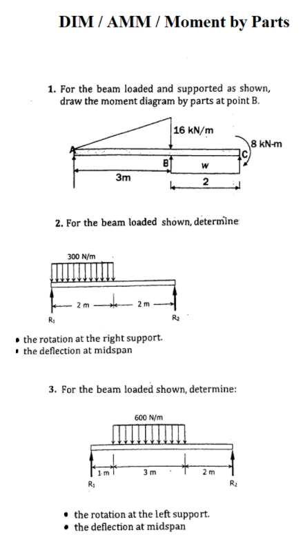
Solved DIM / AMM/ Moment by Parts 1. For the beam loaded and | Chegg.com Engineering Mechanical Engineering Mechanical Engineering questions and answers P11.3 A beam is loaded and supported as shown in Figure P11.3. (a) Use the double-integration method to determine the reactions at supports A and B. (b) Draw the shear-force and bending- moment diagrams for the beam. FIGURE P11.3 This problem has been solved!

Source Image: chegg.com
Download Image
Solved A beam is loaded and supported as shown, with F = 2.8 | Chegg.com
Solved DIM / AMM/ Moment by Parts 1. For the beam loaded and | Chegg.com Step by step Solved in 2 steps with 1 images SEE SOLUTION Check out a sample Q&A here Knowledge Booster Learn more about Axial Load Need a deep-dive on the concept behind this application? Look no further. Learn more about this topic, mechanical-engineering and related others by exploring similar questions and additional content below.
Find the support reactions of the beam loaded as shown in the figure. #mechanical #engineering – YouTube The beam supports the triangular distributed load shown below with wmax=500 lb/ft. The reactions at A and B are vertical. a. Determine the resultant shear force on the cross section at point 3,508 solutions Advanced Engineering Mathematics 10th Edition • ISBN: 9780470458365 (1 more) Erwin Kreyszig 4,134 solutions Statics and Mechanics of Materials: An Integrated Approach 2nd Edition • ISBN: 9780471434467 Don H Morris, Leroy D Sturges, William F Riley 612 solutions More related questions engineering